

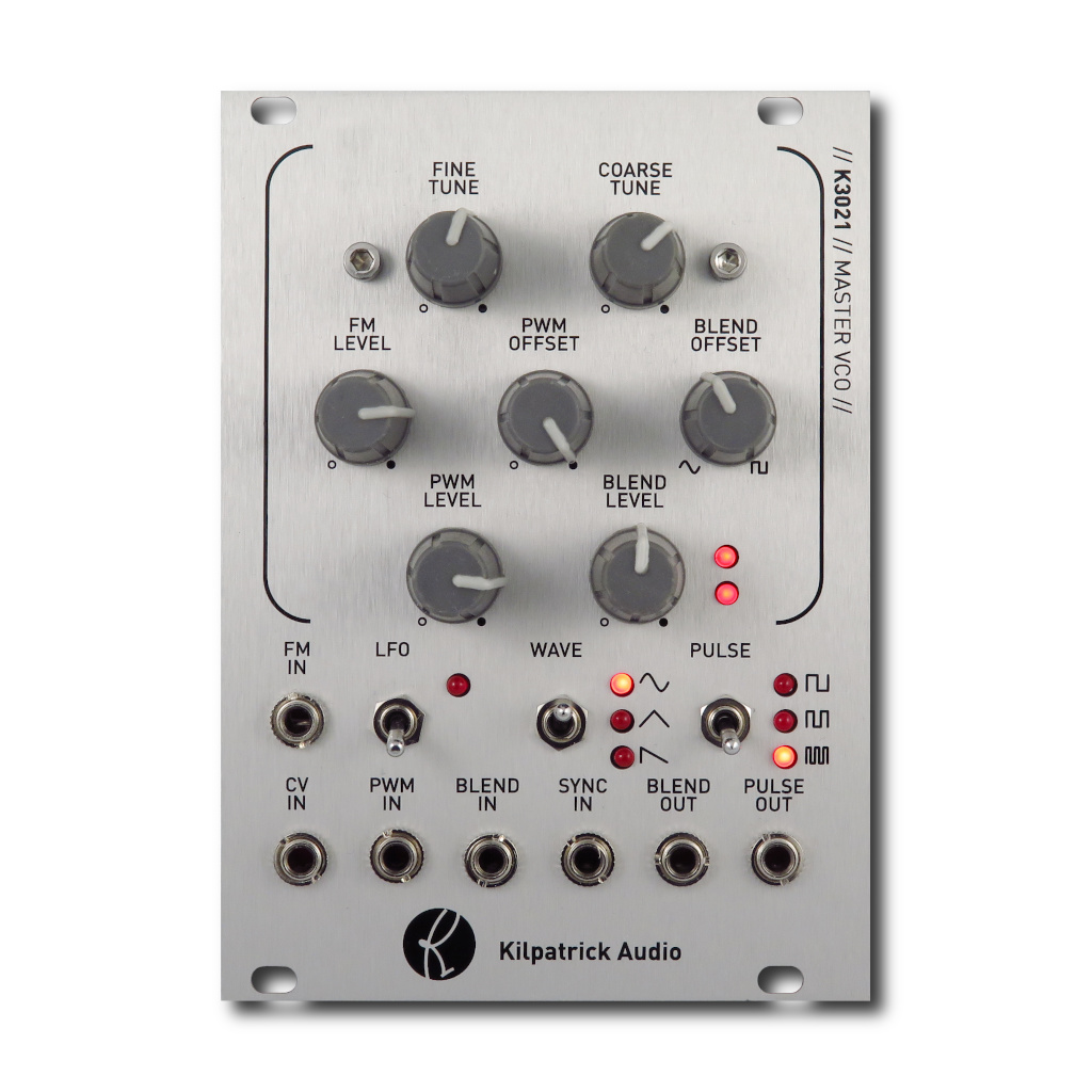
K3021 Master VCO
User Manual
Download a PDF version of the manual here: K3021-master_vco-manual.pdf
Note that PDF manuals are automatically generated from webpages. Links and embedded media will not be accessible. For the full experience visit our website: www.kilpatrickaudio.com
Introduction
When we released the original K3020 Dual VCO back in 2011 people were amazed by the sound and flexibility of the module. The unique blend circuit, stability and excellent PWM section became a favourite amongst serious modular players. But unfortunately all good things must come to an end. Some of the components used in the K3020 are no longer available. As well, modern players now request more compact modules. Thus the K3021 was born! The K3021 Master VCO aims to recreate the flexibility and excellent sound of the K3020 in a small and affordable package. We hope you will enjoy the K3021 Master VCO!
Setup
The K3021 Master VCO requires only +12V and -12V. Make sure you use a good power supply that is not overloaded. The voltages should measure as close to +12V and -12V as possible.
The easiest way to get started is to just listen to the output from the BLEND OUT jack and adjust the tuning controls, WAVE switch and BLEND OFFSET control to check out the various waveforms.
All signals on the K3021 use a range of about -5V to +5V. (10V peak to peak) The exception is the SYNC IN jack which requires a sharp positive going voltage to trigger.
Jacks and Controls
Tuning and Range
The fine and coarse tuning controls are used to tune the module. The COARSE TUNE control has a range of most of the output range of the module, and the FINE TUNE operates over about half an octave.
The LFO puts the K3021 into low-frequency oscillator (LFO) mode. By using the blend and pulse functions, very complex LFO waveforms can be produced. Two LEDs beside the BLEND LEVEL control show whether the internal oscillator core voltage is rising or falling. This can be useful when in LFO mode.
CV IN, FM IN and FM LEVEL
Tuning CV voltages go into the CV IN and FM IN jacks. The CV IN jack is internally calibrated to respond exponentially with 1 volt per octave and should work with MIDI to CV converters or other sources of musical pitch voltage. The FM IN jack responds linearly and can be used for special effects, vibrato, and so on. It is possible to stop the oscillator with a low enough voltage on this jack. The FM LEVEL control attenuates the FM IN signal. It should be turned all the way down when not in use.
WAVE Switch
The WAVE switch selects which waveform is used as the source of sound within the K3021. You can choose between sine, triangle and ramp waveforms. These are output on the BLEND OUT jack and are also used to drive the PWM circuits internally.
PWM / PULSE Controls
The PWM circuit in the K3021 is special in that there are actually three complete PWM units. The PULSE switch selects which combination of these units are mixed together using an XOR function to create unique and colourful waveforms. You can choose one, two or three pulses with the PULSE switch.
The PWM OFFSET control affects the pulse width and shape of the pulse waveforms. Note that in some pulse modes there are spots where very thin / barely audible pulses are generated in the centre of the control range. This is normal.
The PWM IN jack and PWM LEVEL control allows an external signal to be used to adjust the PWM offset. The PWM LEVEL control attenuates the external input.
The PULSE OUT jack produces only the output from the PWM circuits. The BLEND OUT jack can produce a mix, or blend of the PWM output and WAVE output. Note that the WAVE selection affects the PULSE output because the chosen waveform is used as the input to the PWM circuits.
Blend Controls
The blend circuit is a unique feature that allows the K3021 to mix between the WAVE and PULSE outputs. The mixture comes out of the BLEND OUT out jack. This approach allows excellent timbral variation without the need for a filter.
The BLEND OFFSET control affects the overall blend between WAVE and PULSE. Counter-clockwise produces WAVE output and clockwise produces PULSE output.
The BLEND IN and BLEND LEVEL controls allow an external signal to be used to vary the blend mix amount. Use the BLEND LEVEL control to attenuate the input signal. The BLEND LEVEL control should be turned down when not in use.
Hard Sync
The SYNC IN jack is used to hard sync the oscillator to another source. A rapidly changing pulse or ramp waveform is needed to reliably reset the oscillator core.
Audio and Control Voltages
Kilpatrick Audio strives to make products with the most convenient and universal voltage standards possible. We believe in the approach that everything should be able to patch into everything and therefore all our modules are based around the most universal -5V to +5V range. Pulses and gates are 0V off / +5V on. Pitch voltages range from -5V to +5V and use the standardized 1 volt per octave scaling. Audio, LFO and envelope voltages also range from -5V to +5V. This gives the absolute best compatibility between different module types. Our non-Eurorack products also follow this same system.
Whenever you see an offset control on one of our modules that is mixed with a CV input, there is an easy way to picture how it works. Simply imagine the offset control setting the value of the particular function with no input signal. (or a 0V input signal) Putting a CV signal into the corresponding input jack will simply add or subtract from this offset setting. Some inputs have attenuator controls (we call them LEVEL) that allow you to scale the input signal. This simply scales down the input signal before it can affect the internal circuitry.
Pitch Calibration
WARNING: If you are not comfortable with basic electronics adjustments please have a more technical friend help you.
Every K3021 is calibrated in our workshop based on a well-calibrated 1V/octave source. However over time and in different setups you might find that pitch tracking needs adjustment. Please follow the procedure below to perform the adjustments. You will need to have the K3021 powered up but accessible fron the rear while doing this. Be careful not to short out parts of the board whil you do this.
Things you'll need:
- Calibrated voltage source - A MIDI to CV converter or some other source of calibrated voltages that you can easily adjust over about an 8 octave range.
- Small flat screwdriver - Make sure it can easily fit into the small brass screws on the blue trim pots on the rear of the module.
- Digital tuner or other pitch source - Even if you have a good ear it's hard to accurately assess very low or high frequencies needed for calibration.
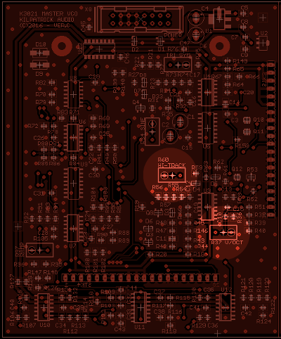
To calibrate the module:
- Locate the trim pots - Located HI-TRACK (R60) and V/OCT (R37) as shown in the image above. These are 25-turn pots and can take a lot of turns to fully deflect in either direction.
- Turn down the HI-TRACK (R60) - Start with HI-TRACK at the minimum position. Keep turning counter-clockwise until either you've turned it 25 times, or you can hear or feel a small click.
- Input the calibrated voltage source - Input the voltage to the CV IN jack and choose a mid-rate note so the pitch doesn't change much when you plug or unplug the CV IN jack.
- Set the FINE and COARSE tuning controls - Make sure the front tuning controls are in a mid position and tune to a known note you can see easily on your tuner.
- Check the scale span - Using the CV source sweep up and down by octaves and check on your tuner to see if the pitch scale is too small: low notes are sharp while high notes are flat, or too large: low notes are sharp while high notes are flat.
- If the scale is too small - increase V/OCT by a turn or so
- If the scale is too large - decrease V/OCT by a turn or so
- Go back to step 4 - repeat until the tracking is pretty in the low and mid frequencies
- Adjust the HI-TRACK - With analog oscillators it's common for high frequencies (above 1-2kHz) to droop due to natural limitations in the electronics. For this reason the HI-TRACK adjustment can be used to compensate for this. Once you've got good tracking over most of the lower range, adding a bit of HI-TRACK can help to raise the high frequencies to get good tracking over a wider range. Note that it may be necessary to repeat steps 4 and 5 after adding HI-TRACK to get things perfectly dialed in.
Need Help?
Feel free to contact us for more information, to report errors or unclear sections, or to request specific information be added to this manual.