

K6101 Dual Envelope
User Manual
Download a PDF version of the manual here: K6101-dual_envelope-manual.pdf
Note that PDF manuals are automatically generated from webpages. Links and embedded media will not be accessible. For the full experience visit our website: www.kilpatrickaudio.com
Introduction
The K6101 Dual Envelope module from Kilpatrick Audio is a Eurorack version of the famous PHENOL envelope generator. This was created by popular demand and will definitely add a new level of creativity to your modular system.Setup
The K6101 Dual Envelope requires only +12V and -12V. Make sure you use a good power supply that is not overloaded. The voltages should measure as close to +12V and -12V as possible.
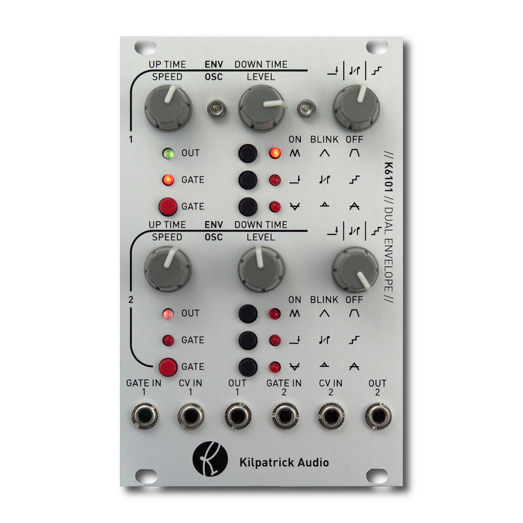
To get something happening right away, turn the third knob on the top row all the way up. Turn the left two knobs up half way. Set the top group of black buttons so that only the top one is on. This puts the first channel into oscillator mode. Patch the OUT 1 jack to the pitch input on an oscillator. Try turning down the third knob to quantize the output!
Jacks and Controls
The K6101 is a dual channel unit. Other than sharing some circuitry and a panel, the two channels function completely independently of each other. Note that buttons are used to change modes. These settings are automatically stored in non-volatile memory and should restore the previous setting when power is applied.
The function of each of the jacks is as follows:
- GATE IN 1 / 2 - Trigger the envelope - in oscillator mode this input can be used to momentarily trigger the oscillator
- CV IN 1 / 2 - Adjust the envelope time or oscillator speed - this signal will add or subtract from the current panels settings
- OUT 1 / 2 - The envelope or oscillator signal output - the output voltage can range from -5V to +5V - an LED above the GATE button shows the output level as red, (negative voltage) green (positive voltage) or off (near zero volts)
Controls
The function of each control is as follows:
- UP TIME / SPEED KNOB - Sets the up time (envelope modes) or oscillator speed (oscillator mode)
- DOWN TIME / LEVEL KNOB - Sets the down time (envelope modes) or output level (oscillator mode)
- THIRD KNOB - Has three possible modes which are set with the third knob mode button (described below)
- GATE - Button to manually generate a gate signal - also has an LED that shows when the gate is on
- Envelope / Oscilltor Mode Button - Top button selects between the main oscillator / envelope modes as described below
- Third Knob Mode Button - Middle button selects between one of three modes for the third knob
- Output Mode Button - Bottom button selects between one of three output modes
Oscillator / Envelope Modes
You can operate the K6101 channels in two different envelope modes or an oscillator mode. The modes are described below:
Oscillator Mode

Top mode LED will be on in this mode. In oscillator mode the output generates a triangle wave. The speed is variable using the first knob, and the output level is varied with the second knob. When you turn on oscillator mode, the gate will be latched on automatically. By pressing the gate button or inputting a gate signal, you can operate the oscillator in momentary mode. To reset the latch, turn oscillator mode off and back on again.
Attack-Release Mode

Top mode LED will be blinking in this mode. In attack-release mode, the output will ramp up at a time set by the first knob (UP TIME) and fade back down automatically at a time set by the second knob. (DOWN TIME) The length of the gate has no effect on the envelope output.
Attack-Hold-Release Mode

Top mode LED will be off in this mode. In attack-hold-release mode, the output will ramp up at a time set by the first knob (UP TIME) and stay at the maximum value as long as the gate signal is present. When the gate is released the output will ramp down with a time set by the second knob. (DOWN TIME)
Third Knob Modes
The third knob can be assigned to affect three different parameters. The middle mode button selects the mode. These are described below:
Gate Delay Mode

Middle mode LED will be on in this mode. The third knob will adjust the gate delay. When a gate signal is input or the gate button is pressed, a timeout must occur before the gate will trigger. Turn the third knob to adjust the delay. The delay only affects the gate turning on. When the gate is removed the output will change immediately.
Scales Mode

Middle mode LED will blinking in this mode. The third knob will adjust which one of 16 pre-programmed scales and arpeggios are used to quantize the output. The output is calibrated by design but might not be exactly 1V/octave. The included scales are as follows:
- 5ths
- 5ths and 7ths
- major
- major 7th down
- minor
- minor 7th
- minor 7th down
- minor alternating
- major alternating
- minor alternating 7ths
- major alternating 7ths
- clusters 1
- clusters 2
- jumping
- blues
- leading
Steps Mode

Middle mode LED will be off in this mode. The third knob will adjust the amount of quantization or the number of steps in the output. The range goes from 2 steps (minimum setting) to fully smooth. (maximum setting)
Output Modes
The output can be presented in three different ways based on the setting of the third mode button. These modes are described below:
Inverted Output Mode

Bottom mode LED will be on in this mode. In this mode the output will be inverted. Instead of ranging from -5V to +5V, the output will range from +5V to -5V. When the envelope or LFO is not running, the output will sit at +5V.
Absolute Value Mode

Bottom mode LED will be blinking in this mode. In this mode the output will produce an absolute value and will only go from 0V to +5V. By using the Steps mode in the lowest setting, you can create +5V pulses and gates to drive other modules.
Normal Mode

Bottom mode LED will be off in this mode. In this mode the output will range from -5V to +5V. When the envelope or LFO is not running, the output will sit at -5V.
Audio and Control Voltages
Kilpatrick Audio strives to make products with the most convenient and universal voltage standards possible. We believe in the approach that everything should be able to patch into everything and therefore all our modules are based around the most universal -5V to +5V range. Pulses and gates are 0V off / +5V on. Pitch voltages range from -5V to +5V and use the standardized 1 volt per octave scaling. Audio, LFO and envelope voltages also range from -5V to +5V. This gives the absolute best compatibility between different module types. Our non-Eurorack products also follow this same system.
Whenever you see an offset control on one of our modules that is mixed
with a CV input, there is an easy way to picture how it works. Simply
imagine the offset control setting the value of the particular function
with no input signal. (or a 0V input signal) Putting a CV signal into
the corresponding input jack will simply add or subtract from this
offset setting. Some inputs have attenuator controls (we call them
LEVEL) that allow you to scale the input signal. This simply
scales down the input signal before it can affect the internal circuitry.
Need Help?
Feel free to contact us for more information, to report errors or unclear sections, or to request specific information be added to this manual.